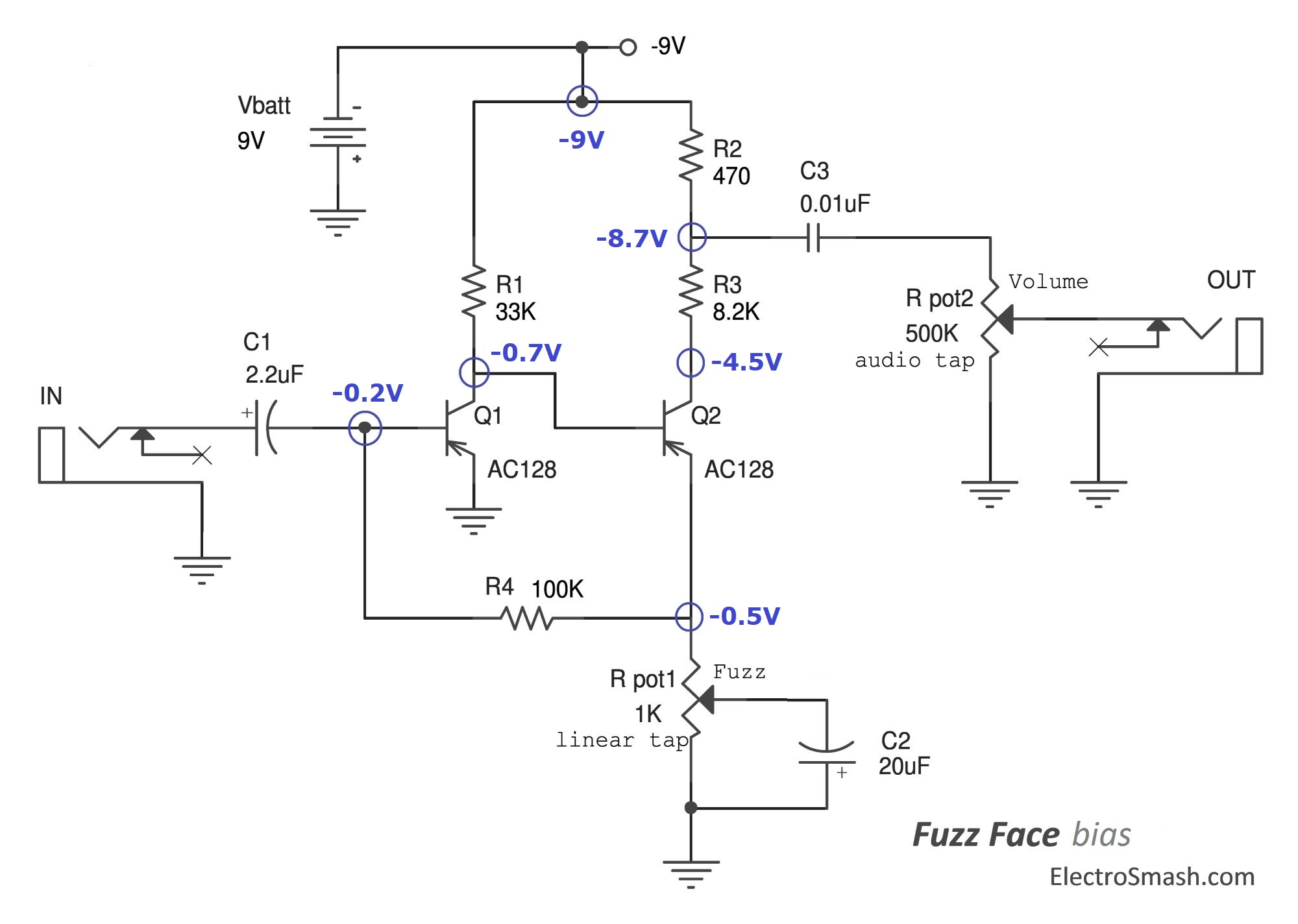
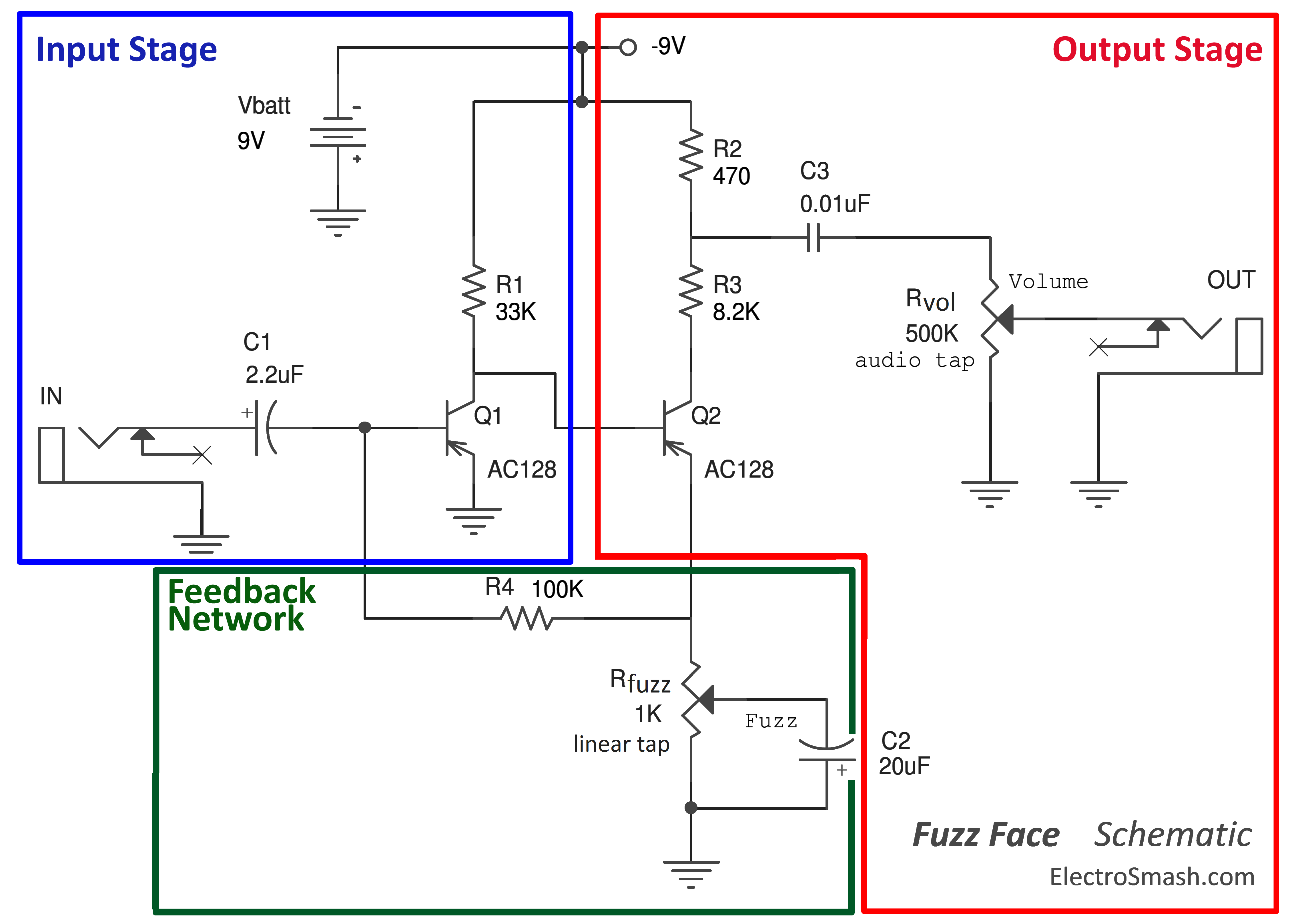
Fuzz Face Schematic
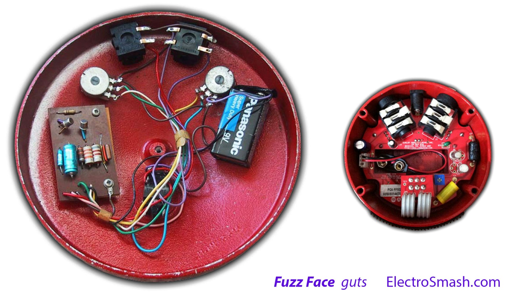
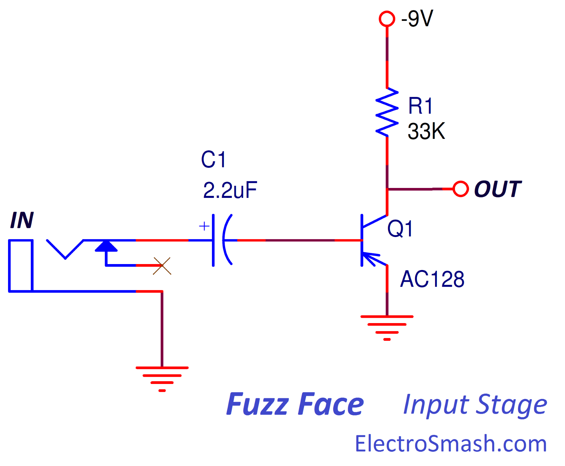
Electrosmash Fuzz Face Analysis
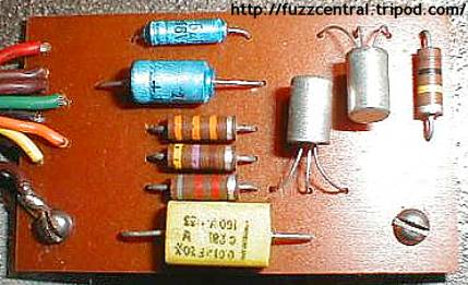
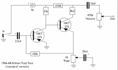
Fuzz Central Arbiter Fuzz Face
Input Buffer For Fuzz Face

Fuzz Face Clone And Clean Boost Veroboard Circuits Diypedals

Fuzz Face Guitar Effects Pedals Schematics Esquemas Eletronicos Pedal De Efeitos Eletronica
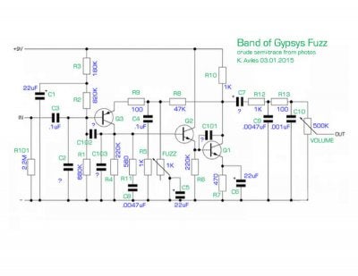
Perf And Pcb Effects Layouts Dunlop Band Of Gypsys Fuzz Face
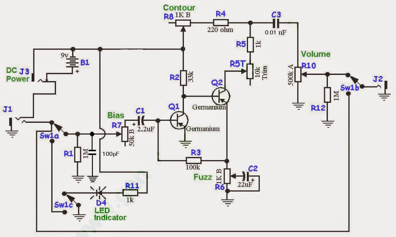
Although the core of the BOG is a modified Fuzz Face circuit, here we don’t like to stop where everyone does So, like all Deep Trip pedals, the BOG takes the usual 9V, center negative power supply, as most standard pedals do No hassles here, no exclusive power supply, no polarity inversion needed, plain simple.

Fuzz face schematic. Big Muff Pi, think The Isley Brothers’ That Lady The rule of thumb is that the more you try to ‘fix’ the idiosyncrasies and inconsistencies in the classic Fuzz Face circuit, the less it sounds like one which can be a good or a bad thing, depending on your tastes. So I could buy a used fuzz face at a good price (love the big round smiling face!) and send to him to put an axis circuit inside I also have a fulltone octafuzz Think the fuzz only sounds quite nice Since I sold the Hendrix, the octafuzz has been my go to fuzz Heard that the new Dunlop bog ff is an octavia without the octave, and from some. (0301) Isle of Tone Haze 67 Fuzz vs Original 1966 Arbiter Fuzz Face by HigherLandrons (0326) History of the Fuzz Face British Guitar Gear Series by The Guitar Show Reviews.
The BC108, for example, which I have seen specified in many old schematics for the silicon Fuzz Face, might have a gain of anywhere from 80 to over 0 depending on what factory made it and when The problem is similar with any of the other NPN silicon devices that are commonly substituted for it. This is a follow up to my video on using a breadboard to build your own Fuzz Face circuit If you want to take that circuit and get it into an enclosure, thi. The reply is a convincing NO unless of course there’s something totally new to become offered that provides this tired old device newer and more effective existence.
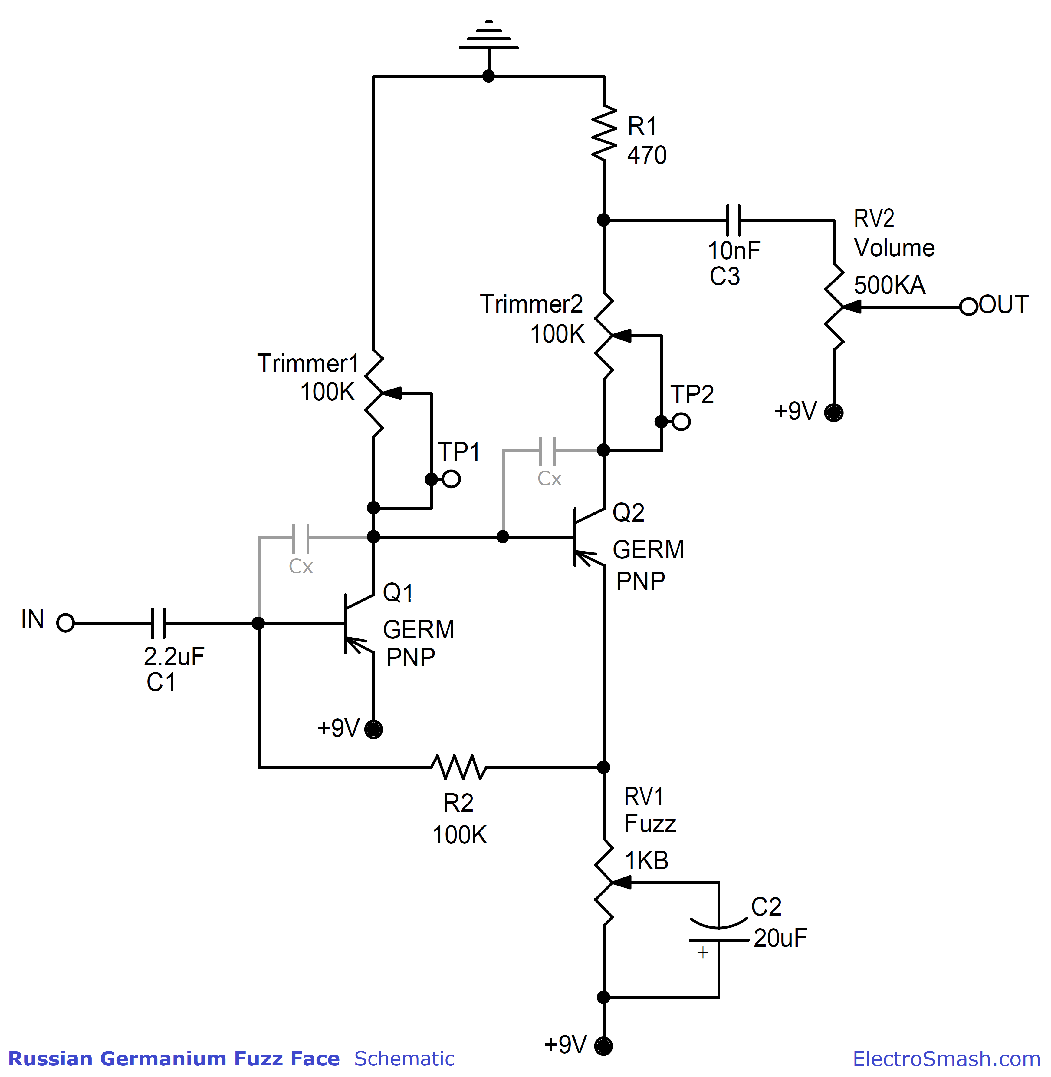
Here are layouts for both germanium and silicon versions of the Fuzz Face, both based on schematics from generalguitargadgets I didn’t go into any details about what transistors to use since this information is readily available just about anywhere else Update () The silicon variant is now verified, thanks to Hookey. Another application of the Bazz Fuss design is the Buzz Box, also designed by Christian The circuit is simply two BF in series, but the second BF stage uses a germanium diode rather than the usual silicon The circuit produces a nasty (in a good way), explosive octaveup fuzz similar to the Scrambler and Green Ringer Listen to the Buzz Box!. The circuit schematic and Bill of Materials are available and open to modifications The Circuit The circuit follows the original Fuzz Face (positive ground) signal path design The pedal uses a double PNP transistor stage and a feedback network The only two differences with the original circuit are.
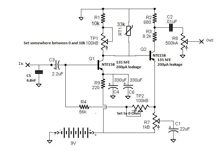
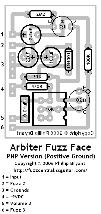
For the Fuzz Face circuit to be optimally biased, the collector of Q2 needs to be at 45 volts (When connecting the Arbiter Fuzz Face Clone circuit to your multimeter as shown in the photos below your meter will read 45v) The K trim pot is used to dial in this value. Arbiter Fuzz Face Clone Biasing Guide Congratulations, that’s the end of the instructions for the Arbiter Fuzz Face Clone circuit!. General Information Arbiter Fuzz Face PNP (Germanium) PNP Germanium Fuzz Face PCB and Layout Arbiter Fuzz Face NPN (Silicon) Arbiter Fuzz Face Reissue Dallas RangeMaster Booster.
More than any other circuit I can think of, the Fuzz Face performs differently according to the effects you combine it with It hates buffers — placing a buffer (or buffered effect, such as most Boss or Ibanez pedals) before the Fuzz Face yields a thin, harsh sound Fuzz Faces almost always sounds best first in the signal chain. Schematics and Printed circuit board layouts for rare pedals like the Tycobrahe Octavia, Clyde McCoy wah and lots of vintage fuzz pedals!. Update 1/03 We can offer our mod on the ROGER MAYER blue rocket "The Fuzz Face" pedal, using the existing circuit board We change all the components on the board but 2 capacitors The FUZZ pot used is a little higher so it can get a little crunchier and more fuzz We can change that to our standard FUZZ pot for an additional $10.
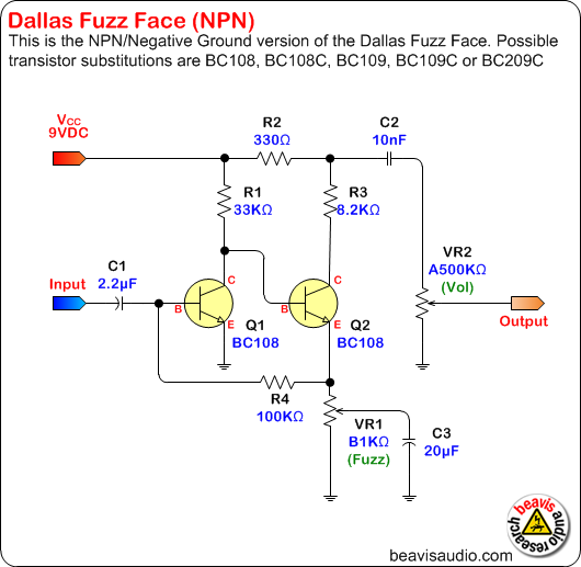
The early Fuzzface units utilized germanium pnp transistors simply because they were the semiconductors most available and reliable at the time The schematic below shows the circuit of this classic unit You will note that the positive battery connection is grounded and the circuit uses a negative supply voltage. We audit all pairs in the classic Fuzz Face circuit, and we guarantee proper operation in that circuit and with the bias resistor values that we specify. Here's a schematic of the last of the original DallasArbiter Fuzz Faces, the NPN Silicon The New Fuzz FacesArbiter Reissues In recent years there has been a huge resurgence of interest in the original Arbiter Fuzz Faces, probably fueled by the very mediocre sounding Dunlop Fuzz Faces.
This is a follow up to my video on using a breadboard to build your own Fuzz Face circuit If you want to take that circuit and get it into an enclosure, thi. Fuzz face schematic Will we need another fuzz face derivative?. 2# Fuzz pedal schematic This is Fuzz audio converter circuit It uses two diodes as a feedback circuit of OPAMP IC, LM324 Also, this can make a musical sound that has unusual characteristics And it will limit output voltage, give a hand net between 07Vpp waves square signal.
The reply is a convincing NO unless of course there’s something totally new to become offered that provides this tired old device newer and more effective existence. The Fuzz Face circuit runs on power that is reverse polarity of a more common, Bosstype effect If you plug it in to a daisy chain, the best case scenario is that you will destroy the daisy chain If you plug it in to a daisy chain, the best case scenario is that you will destroy the daisy chain. The Sunface is a Fuzzface slightly modified Fuzz face is really a simple circuit design, as you can already tell by the number of components of the circuit 4 resistors, 3 capacitors and 2 transistors!.
The BC108, for example, which I have seen specified in many old schematics for the silicon Fuzz Face, might have a gain of anywhere from 80 to over 0 depending on what factory made it and when The problem is similar with any of the other NPN silicon devices that are commonly substituted for it. Fuzz Factory Overview Fuzz Factory Project Link The Flare is a clone of the ZVEX Fuzz Factory, a really interesting little box that lets you create everything from a really thick but musical fuzz to some messedup oscillations The Fuzz Factory is essentially a classic Fuzz Face with a LPB1 booster in front of. Here are layouts for both germanium and silicon versions of the Fuzz Face, both based on schematics from generalguitargadgets I didn’t go into any details about what transistors to use since this information is readily available just about anywhere else Update () The silicon variant is now verified, thanks to Hookey.
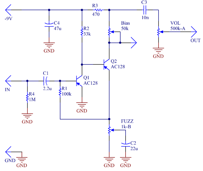
This is the circuit diagram of Fuzz Face mods, guitar effect pedal This is a modified diagram and simpler than the original Fuzz Face diagram You will find apparently two identical designs of the fuzz face In one Q1 and Q2 had been PNP germanium AC128 or NKT275 types, in the other they had. Will any/all of your pairs work in the various clones of the germanium Fuzz Face, eg, the Vox Tone Bender, Fuller Mods, Hendrix Mods?. Fuzz Face Analysis The Fuzz Face is a distortion guitar pedal designed in London by Arbitrer Electronics Ltd in the autumn of 1966 It produces a characteristic high distorted sound called fuzz Ivor Arbiter took the round shaped enclosure idea from a microphone stand and it was the first pedal including a DPDT stompswitch.
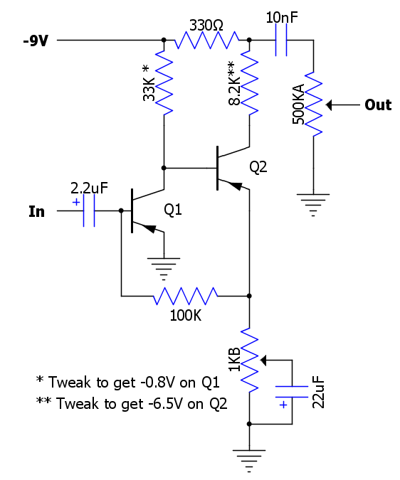
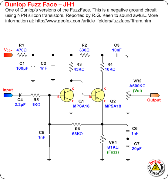
Fuzz Face™ ReadyForTransfer Printed Circuit Board Layout – For use only if you are a complete DIY person who wants to etch and drill your own PCB Otherwise, we recommend you ignore this PCB mask and buy the ReadytoSolder Printed Circuit Board or Complete Kit from the links below. The JH1 and JH2 were both attempts to combine the Fuzz Face circuit with the purchased rights to Jimi's name (bought from the JH estate, as noted on the bottom of the pedal) Both were made with high gain silicon transistors and sounded dreadful (IMHO) The JH2 used the MPSA18, with a typical gain of 900!. Fuzz Face, think Hendrix’s Purple Haze;.
The Fuzz Face circuit runs on power that is reverse polarity of a more common, Bosstype effect If you plug it in to a daisy chain, the best case scenario is that you will destroy the daisy chain If you plug it in to a daisy chain, the best case scenario is that you will destroy the daisy chain. The Fuzz Face is an effects pedal for electric guitar, used also by some electric bass players It is designed to produce a distorted sound referred to as "fuzz," originally achieved through accident such as broken electrical components or damaged speakers. This fuzz is not that big for a vintage fuzz, especially compared to the 1973 Supa Tonebender that I had on my bench before At the front of the pedal, there are two controls Volume and Attack (translate by "Fuzz") It is the second version of the Fuzztone, the FZ1A.
The BC108, for example, which I have seen specified in many old schematics for the silicon Fuzz Face, might have a gain of anywhere from 80 to over 0 depending on what factory made it and when The problem is similar with any of the other NPN silicon devices that are commonly substituted for it. In stompbox lore, the Fuzz Face Distortion sits among the icons Its uncanny ability to add harmonic richness and “hair” around clean tones at lower settings is as satisfying as the fullon roar it wields when dimed and raging With a roster of power users that includes guitar legends and modern heroes from David Gilmour and Jimi Hendrix to. The following diagram is the Jimi Hendrix Fuzz Face Pedal JH2 circuit diagram Schematic by Jim Dunlop Note Q1 & Q2 are MPSA18 Demo sound of Jimi Hendrix Fuzz JH2 The Jh2 has a tendency to fold in on itself and gives the impression that unity gain is unattainable the secret?.
Big Muff Pi, think The Isley Brothers’ That Lady The rule of thumb is that the more you try to ‘fix’ the idiosyncrasies and inconsistencies in the classic Fuzz Face circuit, the less it sounds like one which can be a good or a bad thing, depending on your tastes. This is a follow up to my video on using a breadboard to build your own Fuzz Face circuit If you want to take that circuit and get it into an enclosure, thi. With this video I have tried to cover everything about the Fuzz Face that you would want to learn There's a quick history lesson, a sidebyside comparison.
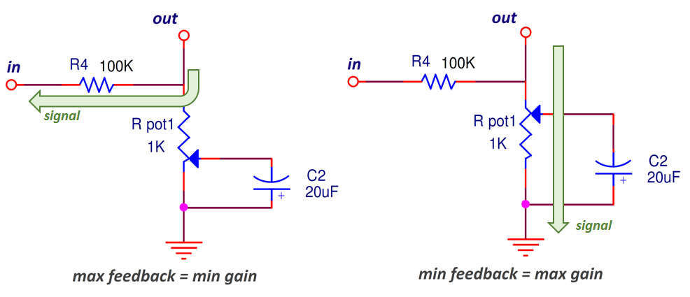
My experience with the EJ was that it was spitty at room volume but at stage volume it was smooth and even Much more disparity in tone with different volumes than other Fuzz Face I've owned So the trimmer is up under the board on both pedals?. Jimi Hendrix used the fuzz sound to pioneer his “psychedelic” sound in the late '60s, and his weapon of choice was the DallasArbiter Fuzz Face pedal With similar controls to the Maestro (volume and fuzz/attack) as well as a pair of germanium transistors, this beast allowed the legendary axeman to get his gamechanging sound. The best way to bias a Fuzz Face (or Rangemaster) is to have a single trimmer for the Emitter resistor on the second stage Instead of using the Fuzz control as the Emitter resistor, use a trimmer, and wire the Fuzz control as a variable resistor in series with the bypass cap (the one normally connected to its wiper).
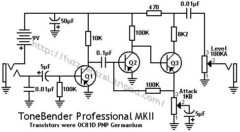
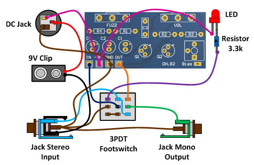
The origin of the Fuzz Face circuit – the early Sola Sound Tone Bender MK II The circuit found in the Fuzz Face appeared first in a competitor’s product, the early version of Sola Sound’s Tone Bender MKII That appeared earlier in 1966(left schematic) The circuit was soon altered by Sola Sound – or perhaps more accurately one of the consultant boffins Sola Sound utilised. Build the circuit as specified in the schematic For now, do now worry about wiring jacks, potentiometers, or anything else that might not attach directly to the circuit board This circuit is basically a 2transistor gain circuit and a variation on the classic Fuzz Face guitar pedal. Fuzz face schematic Will we need another fuzz face derivative?.
Build the circuit as specified in the schematic For now, do now worry about wiring jacks, potentiometers, or anything else that might not attach directly to the circuit board This circuit is basically a 2transistor gain circuit and a variation on the classic Fuzz Face guitar pedal. A lot of people look at the Fuzz Face circuit and think it only has a few components so it must be simple In contrast the simplicity of the Fuzz Face makes it actually quite a complex beast to consistently make well Every small variant has a massive impact of the circuit This is why so many mass manufacturers stay away from it. For this very first post in my new DIY Blog, I’m sharing a vero board layout I created from Jack Orman’s brilliant “negative ground PNP Fuzz” circuit Mr Orman’s brilliant work can be found on his site musiquecom, where he provides incredible insight into the world of guitar effects designBookmark his site, and be sure to order one of his eBooks on the RAT, Big Muff.
The Fuzz Face’s classic appearance includes knobs that look vintage (but are numbered, unlike the originals) The paint is similar, with teardrop markers on the casing and the controls labeled in paint, rather than decals The construction is solid, with solid rubber feet mounted with screws The modern updates – the numbered knobs and. Fuzz Factory Overview Fuzz Factory Project Link The Flare is a clone of the ZVEX Fuzz Factory, a really interesting little box that lets you create everything from a really thick but musical fuzz to some messedup oscillations The Fuzz Factory is essentially a classic Fuzz Face with a LPB1 booster in front of. The JH1 and JH2 were both attempts to combine the Fuzz Face circuit with the purchased rights to Jimi's name (bought from the JH estate, as noted on the bottom of the pedal) Both were made with high gain silicon transistors and sounded dreadful (IMHO) The JH2 used the MPSA18, with a typical gain of 900!.
Update 1/03 We can offer our mod on the ROGER MAYER blue rocket "The Fuzz Face" pedal, using the existing circuit board We change all the components on the board but 2 capacitors The FUZZ pot used is a little higher so it can get a little crunchier and more fuzz We can change that to our standard FUZZ pot for an additional $10. Jimi Hendrix used the fuzz sound to pioneer his “psychedelic” sound in the late '60s, and his weapon of choice was the DallasArbiter Fuzz Face pedal With similar controls to the Maestro (volume and fuzz/attack) as well as a pair of germanium transistors, this beast allowed the legendary axeman to get his gamechanging sound. FUZZ 1KB / 2KB VOL KA Oh my If ever there was an essential addition to a rig then the Fuzz Face surely is it A bit of fiddling will get you anywhere from creamy smoothness to ear.
And the only way to get to it is to detach the board?. Fuzz Face, think Hendrix’s Purple Haze;. Fuzz face schematic” src=”http//circuitbentnet/wpcontent/uploads/18/12/fuzzfaceschematic6_2jpg” title=”Fuzz face schematic ()” /> Now complete the connections to the bottom of the transistor with the addition of a 100K resistor between indices F5 and F9 (Fig 24) The colour code is Brown, Black, Yellow, Gold.
Schematic BOM Classic version Hendrix/Mayer changes shown in blue) R1 100K R2 33K R3 470R / 1K R4 preset 47K C1 22u C2 22u C3 001u Q1,2 So Many Options!!!. (0301) Isle of Tone Haze 67 Fuzz vs Original 1966 Arbiter Fuzz Face by HigherLandrons (0326) History of the Fuzz Face British Guitar Gear Series by The Guitar Show Reviews. Schematics and Printed circuit board layouts for rare pedals like the Tycobrahe Octavia, Clyde McCoy wah and lots of vintage fuzz pedals!.
2# Fuzz pedal schematic This is Fuzz audio converter circuit It uses two diodes as a feedback circuit of OPAMP IC, LM324 Also, this can make a musical sound that has unusual characteristics And it will limit output voltage, give a hand net between 07Vpp waves square signal. Technology of Fuzz Face is a mustread if you’re considering building or modding a fuzz face It has tons of information on the circuit, how to test and select transistors, some mods, etc Highly recommended read. If everything is wired/connected properly, you should have a fully functional fuzz pedal Remember to adjust the trimpot to get the sound you want from your new pedal and have fun!.
The best way to bias a Fuzz Face (or Rangemaster) is to have a single trimmer for the Emitter resistor on the second stage Instead of using the Fuzz control as the Emitter resistor, use a trimmer, and wire the Fuzz control as a variable resistor in series with the bypass cap (the one normally connected to its wiper). Does the Bonamassa have a trimmer as well?. The early Fuzzface units utilized germanium pnp transistors simply because they were the semiconductors most available and reliable at the time The schematic below shows the circuit of this classic unit You will note that the positive battery connection is grounded and the circuit uses a negative supply voltage.
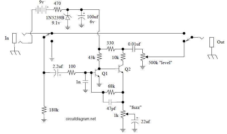
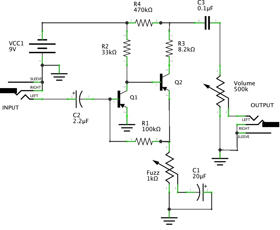
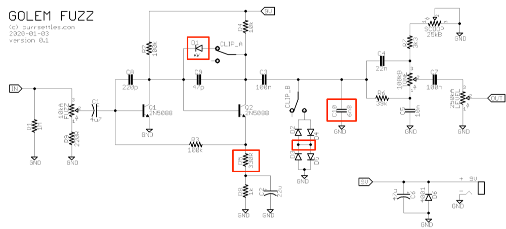
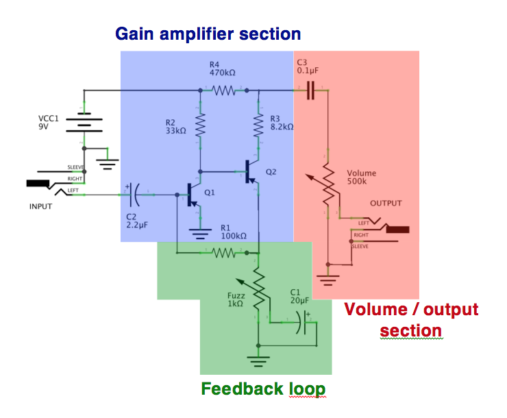
Fig2 Fuzz face circuit, classic 60s original schematics with different sections of the circuit (made with Fritzing) The first capacitor (C2, 22uF) filters the DC current at the entry of the circuit to avoid troubles with the next part of the circuit This kind of capacitor (that you will find in a lot of circuits) is called a coupling capacitor. General Information Arbiter Fuzz Face PNP (Germanium) PNP Germanium Fuzz Face PCB and Layout Arbiter Fuzz Face NPN (Silicon) Arbiter Fuzz Face Reissue Dallas RangeMaster Booster. The Sunface is a Fuzzface slightly modified Fuzz face is really a simple circuit design, as you can already tell by the number of components of the circuit 4 resistors, 3 capacitors and 2 transistors!.
Dunlop Jdf2 Fuzz Face Freestompboxes Org
Build A Fuzzbox Part 1
Jimi Hendrix Fuzz Face Pedal Jh 2 Electronic Schematic Diagram
How To Make A Distortion Into A Fuzz
Fuzz Face Point To Point Diagram Telecaster Guitar Forum
24 Ideas On Creating A Germanium Fuzz Face Guitar Pedal Circuit Bent
Diagram Fuzz Face Wiring Diagram Full Version Hd Quality Wiring Diagram Guitarschematicn Promozionifarmacie It

Pin On Guitar Effects
Q Tbn And9gcsadwsmrurehqgcwvylyljjgptvm6habupvombizn4 0iaqbfub Usqp Cau

Fuzz Face Analysis Diy Guitar Pedal Fuzz Distortion Guitar

Positive Power For The Pnp Fuzzface

Coda Effects Sunface Fuzzface Circuit Analysis
Technology Of The Fuzz Face Frame Definition

Fuzz Face Effect 2x Top Quality Proffesionally Made Pcb Stompbox Pnp Npn Diy Ebay
Electrosmash You Can Build The Perfect Germanium Fuzz Face
The Pink Face A Silicon Fuzz Face Circuitlab

Original Pnp Germanium Fuzz Face Schematic Pedais De Guitarra Pedal De Efeitos Eletronica

One Knob Fuzz
Fuzz Central Arbiter Fuzz Face
Diy Guitar Pedal Blog Axis Fuzzface Silicon

Fy 2 Germanium Fuzz Face Germanium Mod

Jimi Hendrix Fuzz Face Ultimate Guitar
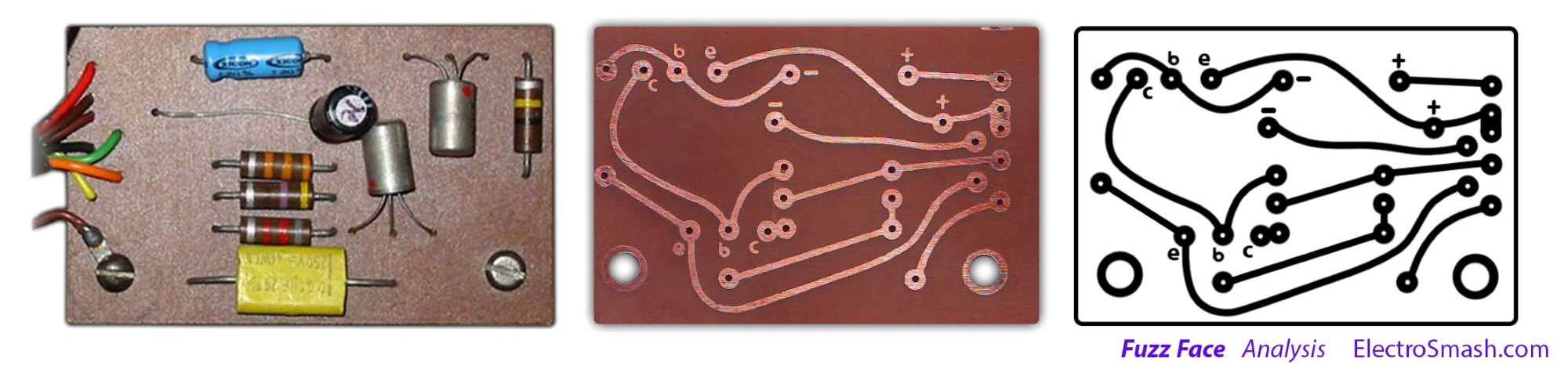
Electrosmash Fuzz Face Analysis

Fuzz Face Using 2n50 2n3904 Will It Works

Perf And Pcb Effects Layouts Npn Fuzz Face
Fuzz Central Arbiter Fuzz Face

The Arbiter Silicon Fuzz Face Doctor Tweek S Blog
Fuzz Face Npn And Pnp Thefretboard

Silicon Fuzz Face Corvy
Fuzz Face
The Fuzz Face

Amz Fx Guitar Effects Blog Blog Archive Fuzz Face Calculator Amz Fx Guitar Effects Blog

Dunlop Jh F1 Jimi Hendrix Fuzz Face Page 5 Freestompboxes Org

Debugging Npn Fuzz Face First Layout

Sili Face Ii
Fuzz Face
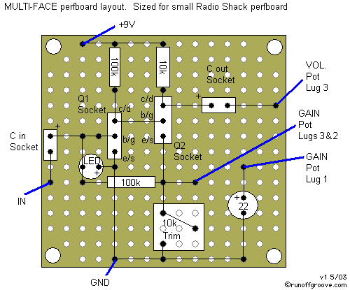
The Multi Face

Sili Face

Positive Power For The Pnp Fuzzface

Category Fuzz Face Schematic Circuit Bent
Fuzz Face Volume Pot Treble Bleed
Fuzz Face Revisited Diy Fever
Coda Effects Sunface Fuzzface Circuit Analysis
Beavis Audio Research Stompbox Schematics
Q Tbn And9gcsf4msdq4cdfkhzjsj8ipjqt2yttp7xunxakwtci4fcafroq7 Usqp Cau

Fuzz Face Davidmorrinoldsite
Electrosmash Fuzz Face Analysis

Fuzz Face Circuit Troubleshooting Question Diypedals

Fuzz Face Rebuilt Pt 2 Drawing Analyzing The Schematic Youtube
Dunlop Fuzz Face Jd F2 Too Much Bass
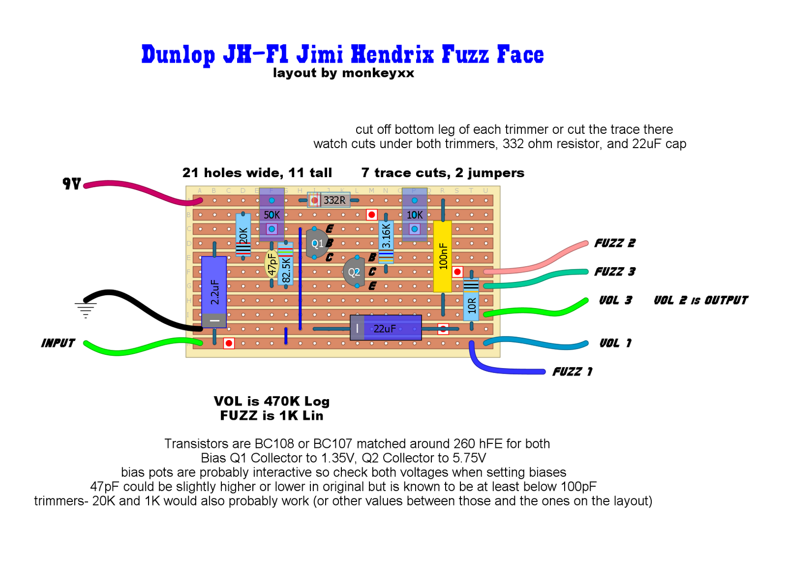
Hendrix Fuzz Face Layout Question

Bias A Fuzz Face Q2 Voltage Fasrlv

Requests Face Bender

Ge Fuzz Face Build Becky S Guitar Tech Blog
Info On Building Myself Something Like The Dunlop Joe Bonamassa Fuzz Face
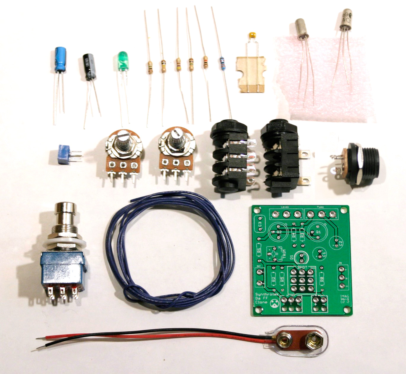
Arbiter Fuzz Face Clone Assembly Instructions Synthrotek

Guitar Fx Layouts Fuzz Face Pnp Negative Ground With Simple Bipolar Power Supply
Circuit Analysis Help Experimental Fuzz
Using A Solderless Breadboard
Http Pedalparts Co Uk Docs Fuzzface Multi Pdf
Beavis Audio Research
Links
Coda Effects Sunface Fuzzface Circuit Analysis
Using A Solderless Breadboard
Fuzz Central Schematics And Pcbs

La Revolution Deux Dunlop Jh F1 Jimi Hendrix Fuzz Face

Tg Music Random Fuzz Face Rant

Fuzz Face Schematic Circuit Bent
Q Tbn And9gcrz4 E0skyuaihzyavmqbolun2ekiyfj4kyiu6llacwxvjlfo1o Usqp Cau

Fuzz Face Circuit Multisim Live

Debugging Negative Ground Fuzz Face Problem
Electrosmash Fuzz Face Analysis

Bazz Fuzz Face Schematic Fuzz Electronics Basics Guitar Effects
Amz Fx Guitar Effects Blog Blog Archive Increase Fuzz Face Output Amz Fx Guitar Effects Blog

View Topic Npn Silicon Fuzz Face Forum Doitfuzz Com

Fuzz Pedal Schematic 1993 Ford F250 Fuel Pump Wiring Diagram Contuor Tukune Jeanjaures37 Fr
History Of The Fuzz Face Sonus Pedals

Schematics Com China Fuzz Face Pcb Schema
Technology Of The Fuzz Face Frame Definition
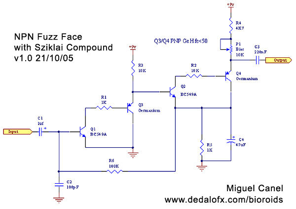
Npn Fuzz With Sziklai Transistor Compound Bioroids Stompbox Electronics

Transfuzzion One 12ax7 Tube And Silicon Fuzz Face Fuzz Guitar Effects Tube
Q Tbn And9gcritsawsiskjidmy5br6mkdhzjmc76lj0jwgmqpscf5jsyklfqd Usqp Cau
Electrosmash Fuzz Face Analysis
Electrosmash Fuzz Face Analysis

One Knob Fuzz
Fuzz Face Circuitlab
Electrosmash Fuzz Face Analysis

D I Y Pro Audio Diy Dallas Arbiter Fuzz Face Build Part 1
Fuzz Central Axis Face Silicon

Hh 53 Reissue Germanium Fuzz Face Circuit Board Wiring Diagram

Stompboxed The Guitar Pedal Builders Repository Fuzz Face Mod 1k Pot
Guitar Gear Ru Forum Index Php App Core Module Attach Section Attach Attach Id
Fuzz Face Si Transitor Advice Please
Courses Physics Illinois Edu Phys406 Sp17 Student Projects Spring14 Robert Lemiesz Physics 406 Final Report Sp14 Pdf

Wiring Diagram Landtone Fuzz Face Ac128 Distortion Ebay Kit G Pcb Diypedals
Fxbus 1 Module 4 A Fuzz Face Style Clipper

One Knob Fuzz

Fuzz Face Led Fender Stratocaster Guitar Forum


